Measuring principle
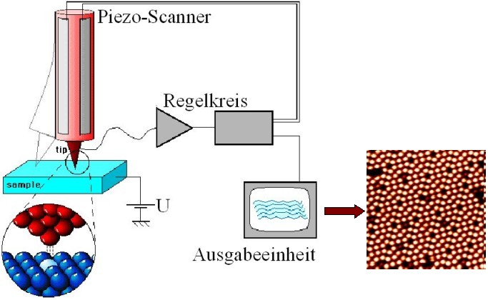
The measuring principle of the STM is based on the quantum mechanical tunnel effect. A thin metal tip and an electrically conductive sample are approximated to within approx. 3 to 10 Å so that the wave functions of the tip can overlap with those of the sample. Ideally, the tip is formed by a single atom. After applying a voltage U (order of magnitude: a few V), an exponentially dependent current I (order of magnitude: nA) of tunneling electrons is measured. In a simple estimation, this current I can be described as follows:
I(d) ~ exp(-A*√Phi*d)
Where A ≈ 1 / (Å * √eV) is a constant and Phi stands for the barrier height of the tunnel contact, which corresponds to the average work function (only in this approximation) of the tip and sample. The tunnel current I is mainly generated by electrons near the Fermi edge EF for which the effective barrier height is the lowest. The ideally mono-atomic tip is moved across the sample line by line with the aid of piezoceramic actuators. The interaction variable can be kept constant via a control loop. The manipulated variable of the control loop, represented as a function of the x and y position of the probe, provides a contour image of a constant interaction variable. For homogeneous samples, this provides a good approximation of the actual topography. To prevent rapid contamination of the surface, most measurements are carried out in a vacuum.
The control loop
In order to keep the distance between the tunnel tip and the sample surface constant, the tunnel current I is kept constant by an electronic control circuit. The control circuit measures the current tunnel current I (actual value) and compares it with the previously set value (target value). If these deviate from each other, the controller attempts to eliminate the difference via its output (control value). The change specifications are transmitted via the piezo elements, which can move the tunnel tip in the three spatial directions. The controller settings depend on the entire system and therefore cannot be set to any desired level. In addition, the control loop itself is already an oscillating system with a cut-off frequency above which natural oscillations occur. These natural oscillations can damage the tip and sample. The scanning speed can have a very strong influence on the quality of the STM image. If the speed is too high, the image usually deteriorates. It must also be remembered that the control speed is closely linked to the scanning speed.
The top of the tunnel
According to electron microscope images, the tunnel tips used have radii of curvature of a few 10 nm. However, as atomic resolution can be achieved on the STM, this can only be explained by the presence of so-called mini-tips. This means that almost the entire tunnel current only flows via the mini-tip closest to the sample. However, the arrangement of these mini-tips on the tunnel tip is by no means stable, but can change in the course of the measurements. This can have both positive and negative effects on the resolution and the general quality of the images. The tunnel tips are usually made of tungsten (etching a piece of wire) or a platinum-iridium alloy (tearing off a piece of wire).
For further information see here.